Nintendo Nes
Circuit bending - modifications
Tutorial

Table of Contents :
1-introduction
2-First Step
3-Lockout chip
4-video out - composite output
5-Audio Modifications
6-Video Bending
7-BONUS
8-Contact


1-introduction
This tutorial offers step by step to mods and circuit bend your Nintendo Nes. This tutorial is also available in French, printable PDF, or in an interactive version on my site:
http://bitcrusher.free.fr/index-eng.phppage=tutones
First Step
1-Part List :
-Nintendo NES
-RCA femal socket ----------->
-2x47 ohms resistor
-2xswitch on/on
-Electrical cable
-2 knob 100 ohms log
-2 capacitor 1uF 50v

-2x6,35 mono jack socket 6,35
-1x6,35 stereo jack socket 6,35
-1 knob 2,2k ohms lin
-Screwdriver
-Soldering Iron
-Dremel
# Step 01/10 Nintendo NES disassembly
Nintendo NES disassembly

-turn the NES back and unscrew the six screws
# Step 02/10 Nintendo NES disassembly

-> In a perfect world, you should get this
# Step 03/10 Nintendo NES disassembly

-Unscrew the 7 screws from the metal cover
# Step 04/10 Nintendo NES disassembly

-> In a perfect world, you should get this
# Step 05/10 Nintendo NES disassembly

-Unscrew the 6 screws of the cartridge holder
-There are two screw that do not have the same length, identify them for futur reassembly.
# Step 06/10 Nintendo NES disassembly

-> In a perfect world, you should get this
# Step 07/10 Nintendo NES disassembly

-Unscrew the two last screws
-Take Gently the circuit board (note that is attached to the NES by cables)
# Step 08/10 Nintendo NES disassembly

-> In a perfect world, you should get this
-Take this opportunity to gently remove the cartridge holder.
# Step 09/10 Nintendo NES disassembly

-Turn back the circuit
-Carefully remove the 3 cable connector.
-Carefully remove the metal covers
# Step 10/10 Nintendo NES disassembly

-> In a perfect world, you should get this
-> Here is the NES is disassembly!
# Step 01/04 LOCKOUT CHIP What is LockOut Chip

This is a security chip implemented by Nintendo to prevent play with imported games: impossible to play on a European NES games with Japanese or American. The problem if you want to use MIDINES with an europeen NES, you can’t.
# Step 02/04 LOCKOUT CHIP Identify and desactivate
-The chip is identified in the circuit by "U10 CIC," and is usually write on top "3195A" (France, Europe) or sometimes "3193A" (U.S.) or "3197A" or "3196A" (Hong Kong).
# Step 03/04 LOCKOUT CHIP Identify and desactivate

-To disable the chip, you must discoinnect the PIN No. 4 of the chip : unsolder it or, more straight forward, cut with a cutter, or destroying it with a Dremel. (mini drill)
# Step 04/04 LOCKOUT CHIP

-I chose the most violent: a little bit of Dremel: here is the result, not very clean, but effective!
-> And here is your NES without area restriction!
# Step 01/06 VIDEO OUTPUT
Why add a composite video output on your NES because the original NES has only one RGB output, suddenly impossible to connect to a computer screen, TV, projector ... The composite output allows it! (note that some European NES has a composite video output)
# Step 02/06 VIDEO OUTPUT

It happens here, zoom and explanation on the next page
# Step 03/06 VIDEO OUTPUT

-Unsolder-R2 (between points A and B)
-Put aside-it will eventually reservir
(if you break it, don’t panic you can replace it with a resistance of 140 ohms.)
)
# Step 05/06 VIDEO OUTPUT
-Connect the middle point of the switch to the point A
-Solder left connection of the switch with resistance R2 (140 ohm that was previously unsoldered to step # 3) then connect to point B
-Solder right connection of the switch with 47 ohm resistor and connect to point B
Solder the second resistance 47 ohms to point C and connect it to the positive connection of the RCA
-Solder RCA negative connection to Point D (ground).
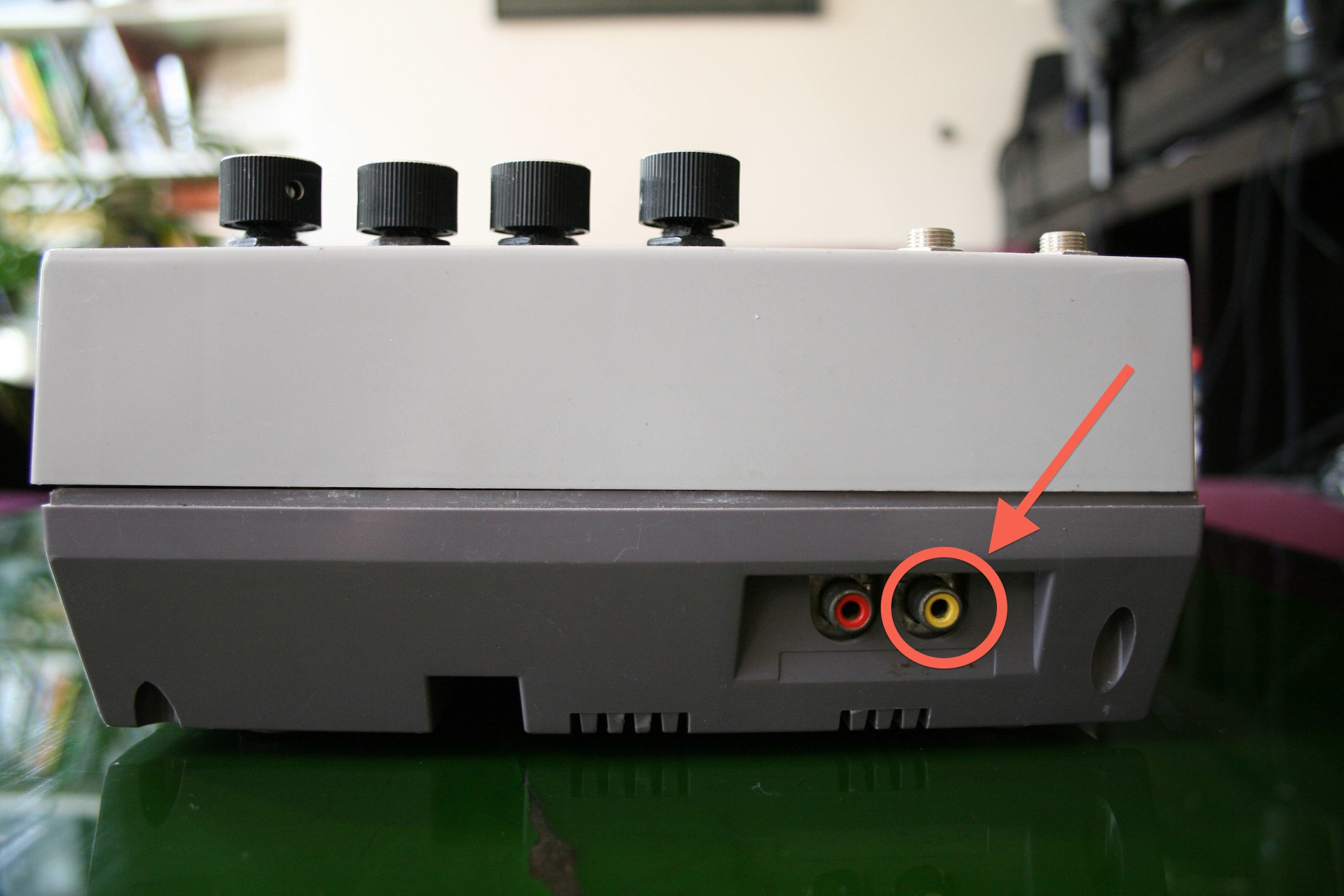
# Step 06/06 VIDEO OUTPUT
Here you have now your composite video output. The interuptor can choose the video output impedance of the NES and avoid having a gray image. There is a position where you are in composite output and another position when you are in RGB output.
# Step 01/06 AUDIO MODS

The sound of the original Nintendo NES is mono although its sound chip is stereo! Nintendo for economical reasons put together the two channels! This modification re-link the sound into 2 channels: one side of the noise osc + TRI + channel wav (rhythm + bass often) and the other channel for osc Pulse. We will take the opportunity to install two separated outputs, plus a stereo headphone socket, as well as the volumes of the two channels.
# Step 02/06 AUDIO MODS
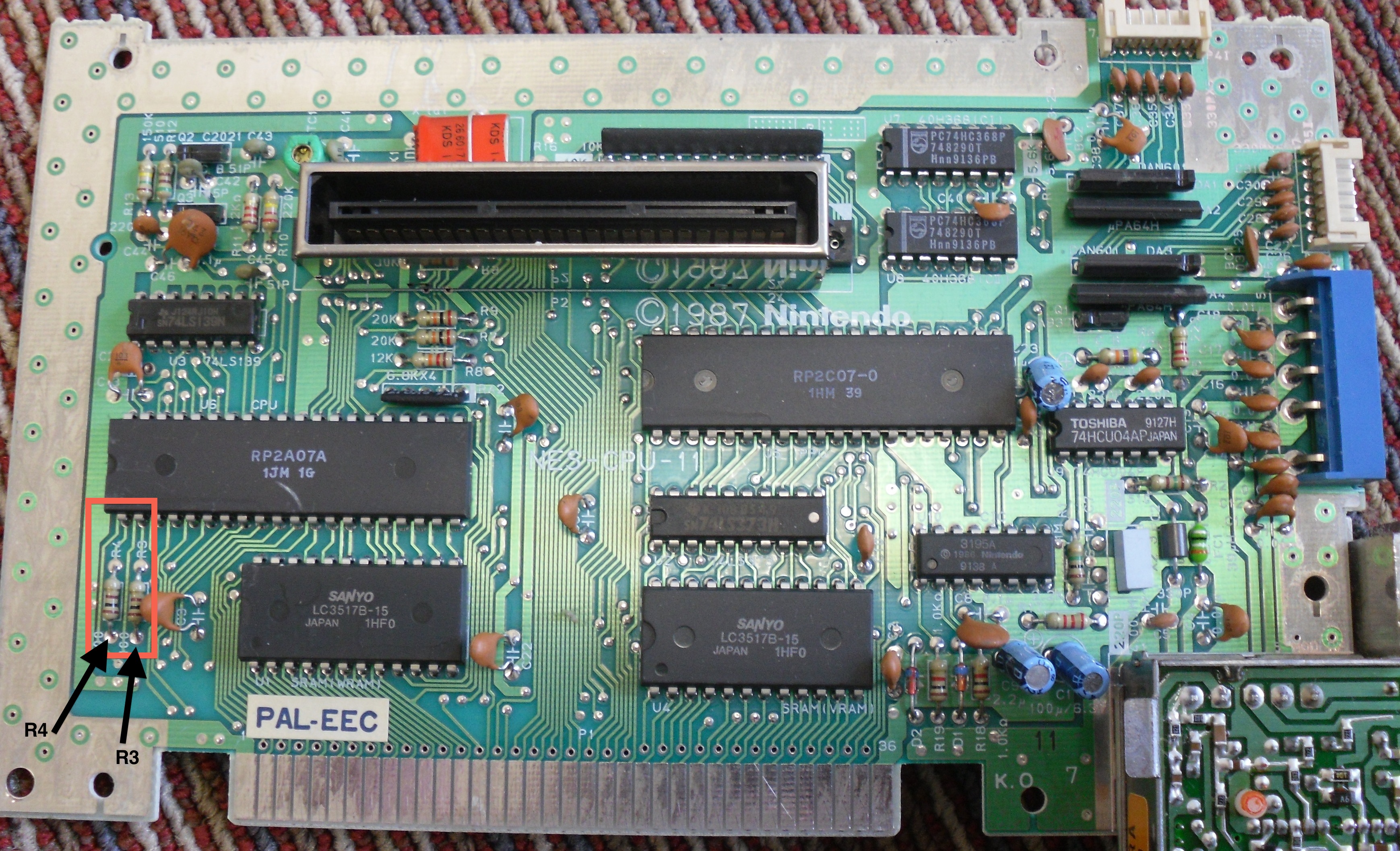
->Locate the two-résitances R4 and R3, which represent the two channels of the NES.
-The pulse-R4 =
-Noise-R3 =, sorting, wav
-> Unsolder them!
# Step 03/06 AUDIO MODS Control Volume of the Channels

-Turn back the circuit, replace resitor you just unsolder with two 100 ohm knob
# Step 03/06 AUDIO MODS Control Volume of the Channels

-> View of the 4 wire used to be connected with two potentiometers 100 ohms.
# Step 03/06 AUDIO MODS Control Volume of the Channels

->overview of the position of the knobs volume of individual tracks, as well as two female jacks 6.35 will be used to separate outputs.
# Step 04/06 AUDIO MODS Separated Outputs

-Solder from point 2 the negative leg of the capacitor 1uF (respect polarity)
-Connect the positive side of capacitor direcetement on the positive leg of the 6,35 jack AudioOut L, connect the negative leg to the ground.Repeat operation starting from point 1
NB : Ground = Point D from step “Video output”
# Step 04/06 AUDIO MODS Separated Outputs

-> Design: I chose to resolder two new wire on the other side of the circuit.
# Step 04/06 AUDIO MODS Separated Outputs

-> Overview under the hood, layout wire, pay attention to fix itself, it will facilitate reassembly of the NES
# Step 05/06 AUDIO MODS Headphone Stereo Output

-Install Stereo 6,35 Jack in parallele of the separate outputs, do not forget to connect the ground to the negative leg of the stereo Jack.
# Step 05/06 AUDIO MODS Headphone Stereo Output
-Overview of the Stereo output
# Step 05/06 AUDIO MODS Headphone Stereo Output

Seen from below, the stereo jack.
# Step 06/06 AUDIO MODS Stereo Imaging

Add in parallel the D knob 2.2 kohms and the C switch. This modification allows to set the stereo imaging of the signal thanks to the D knob you spend full stereo to full mono. The C switch allows you to enable or disable this option.
# Step 06/06 AUDIO MODS - Stereo Imaging

-Wire positioning.
# Step 01/04 VIDEO BENDING

The aim of video-bending is to create visual glitch with the circuit bend of the NES video chip. Here are the results we can obtain:


# Step 01/04 VIDEO BENDING

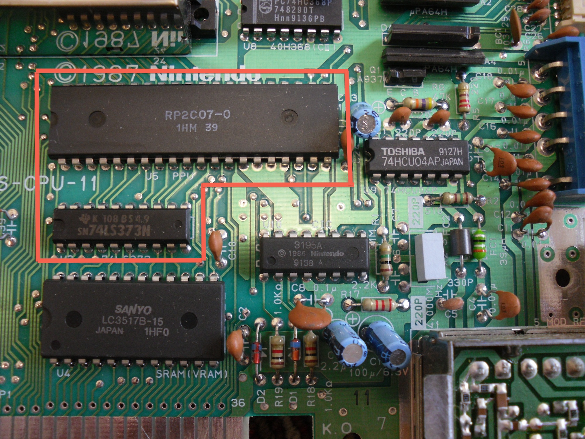
-Here is the 2 target chip :
RP2C07 (on chip); U5 PPU (on circuit)
SN74LS373N (on chip); U2 74LS373 (on circuit). sometimes this chip is named HD74LS373P
# Step 02/04 VIDEO BENDING
For video-bend, simply connect the legs of these circuits in pairs to achieve visual glitch, some combinations are crashing the NES, others do not
# Step 03/04 VIDEO BENDING
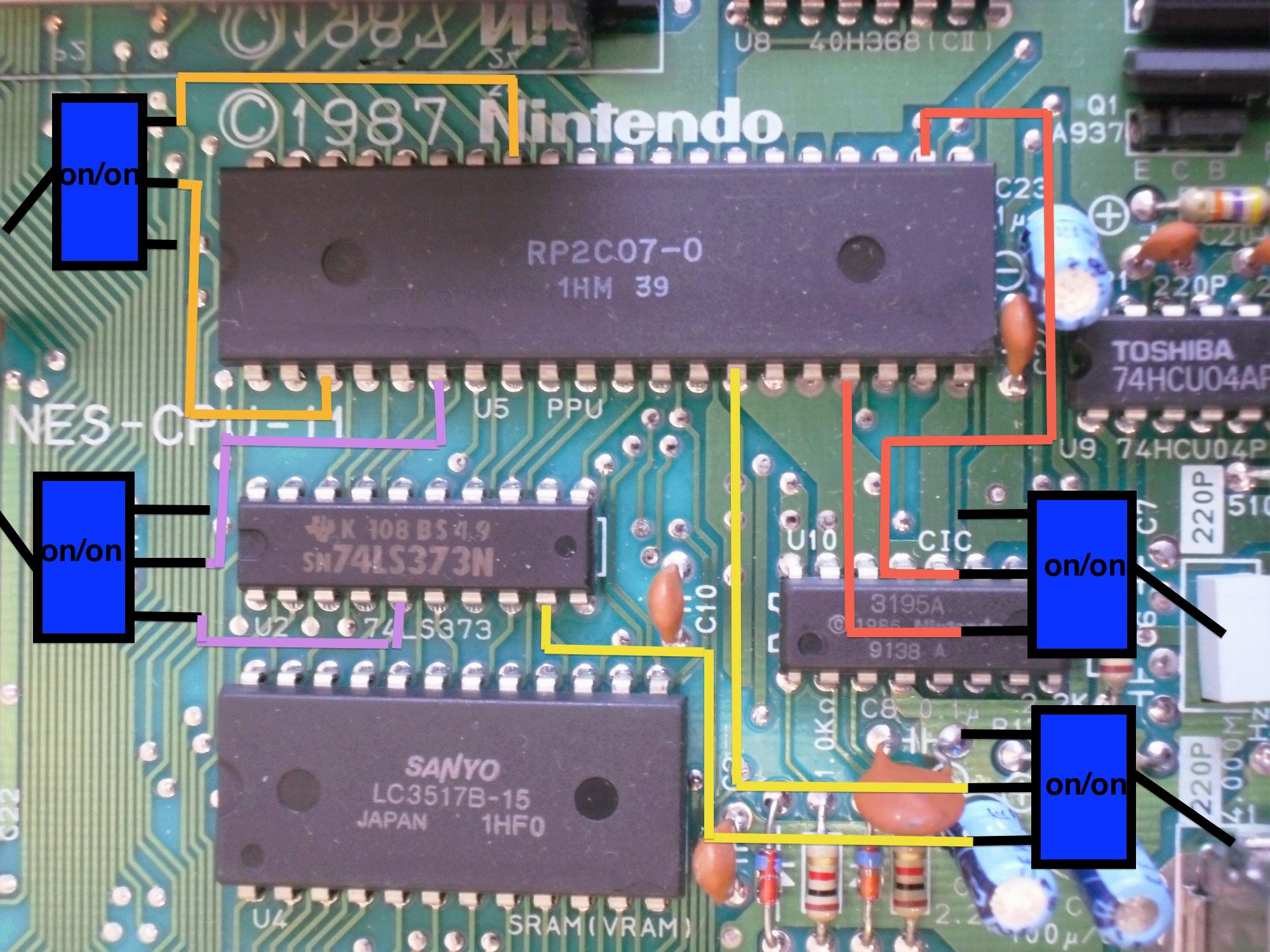
-Once your Selected bend, solder a wire on each chip leg you choose.
Connect wire by pairs to a device of your choice: switch on / on, push button, or RCA jack socket
# Step 04/04 VIDEO BENDING

# BONUS : Restore the cartridge holder
# Step 01/01

-if you want to give to a 2nd youth to your NES and stop NES blinking, you can change the cartridge connector with a new one, you will find ebay, search for “NEW NINTENDO NES 72 PIN CONNECTOR “
# 7 - CONTACT
If you have asking or request :

->There is other tutorial on my website : Dictée magique, TR505, DR220, TB303
HTTP://BITCRUSHER.FREE.FR
->follow : www.facebook.com/Bitcrusher.Bending